With the drive to reduce optical payload form factors and capture data-rich images by utilising CubeSat platforms, payload design challenges arise. Specifically, when looking at the optomechanical design of these payloads. In the development process this is sometimes assumed as a given, as it should be, but achieving this “given” (that the optomechanical design meets al payload design requirement) does take precision engineering, analysis, insight and many iterations. Finite Element Analysis (FEA) does play a vital role in this process and with this piece, we hope to shed some light in the challenges that we face and how we addressed them at Simera Sense.
Payload design challenges
To achieve exceptional ground spatial resolution within compact form factors require innovative optical designs wherein focal lengths and optical apertures are maximised. Achieving this while chasing small form factors can be contradictory requirements to a certain extent. Increasing the optical apertures eats into the volume budget for mechanical components. As a result, the limited volume budget leaves you with little to no room to work with during the payload design process.

Controlling and understanding the effect the integration environment has on small form factor optical payloads is critical to achieving a good payload design. Integration effects could range from the alignment of the optical components, managing the temperature and humidity environment of the cleanroom to the shrinkage of the adhesive during the cure cycle. Each of these factors needs to be addressed and accounted for during the optical payload design process.

Getting the optical payload into orbit and operating in orbit is where the actual tests and challenges arise: the launch and in-orbit environment. Therefore, to develop a robust product range, various launch options must be considered during the structural and optomechanical design phase of the development. Standards such as GSFC-STD-7000 are an excellent guideline for defining vibration environments for your design that would enable you to qualify for launch on a broad range of launch vehicles.
Successfully taking data-rich images from low earth orbit requires the payload design to be operational over a wide temperature range. With this in mind, an operational temperature range of -10 ˚C to 50 ˚C is set as a requirement for Simera Sense’s optical payload designs to ensure that imaging is possible within typical CubeSat thermal environments. Operating over such a wide temperature range requires the optomechanical payload design to be athermal across this temperature range. Furthermore, temperature gradients must be accounted for as well.
All the challenges mentioned above must be addressed as early as possible during the development phase of a new product. Naturally, you would want to address the challenges before any hardware manufacturing kicks off. Various methods are available for solving these payload design challenges, such as structural analysis using Finite Element Analysis, tools to translate structural and thermal effects to optical design software and the optical design software itself.
Solving our Payload Design Analysis Challenges
At Simera Sense, we are using integrated CAD and FEA Software to allow for a concurrent engineering approach instead of having over the wall solutions. NX by Siemens is our weapon of choice for structural design and analysis while we opt for Zemax as our optical design software. Both packages function very well on their own and ease the design process. However, the real value lies in combining the data generated in a Structural-Thermal-Optical Analysis, STOP if you will. The link we have found to enable us to do this efficiently is Sigfit by Sigmadyne. Using this combination of software packages, analysis methods and data translation, we can address the required challenges to meet the performance requirements of market-leading CubeSat optical payload designs.

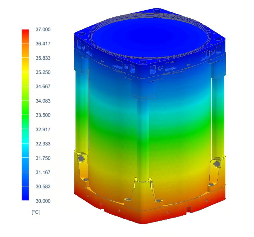
An example of the process would be inspecting the optical performance of a payload when exposed to axial thermal gradients. The first step in the process is to apply the thermal gradient load to the finite element model and calculate the displacements of the optical payload design.

The next step is to extract the displacement data. A job easier said than done. When evaluating displacement and deformation of optical components, there are 3 outputs that your optical analyst is interested in: bulk displacements, bulk translations, and the deformation of the optical surface. We use Sigfit to identify and quantify these disturbances. Below is an example of an optical surface’s deformation when the payload design is exposed to a thermal gradient. In this case, the bulk displacement and translations have already been subtracted; therefore, only surface deformations are visible.

These surface deformations, along with the displacements and rotations, can be applied to the optical model in Zemax, allowing us to evaluate the effect of these disturbances on our optical systems. The surface deformations also account for the change in curvature due to thermal loading. Another critical parameter we need to take into account is changes to material properties due to change in temperature. Most notably, in this case, would be the change in the refractive index of the various optical materials. Accounting for temperature-induced changes in the refractive index can either be done manually using average temperatures or more involved method can be employed using Sigfit.
After accounting for all physical and optical changes in the optical model, we calculate actual expected optical performance values. Therefore, allowing early detection of potential issues and parameter that negatively affect the performance. Cases, where structural requirements are negatively influencing the optical performance of the payload design, can be identified and addressed accordingly. Taking these challenges into account allows us to confidently send out optical payloads to space to taker high-resolution data-rich images that can be used for application such as precision forestry, disaster management, maritime surveillance and much more!
In-Orbit Data Quality is the Key
With the design of complex systems such as CubeSat optical payloads is is easy to lose sight of the bigger picture. In the case of optical payloads, one must always remember that the goal remains to capture data. All the analysis methods and techniques discussed in this piece aid in ensuring that Simera Sense’s optical payloads are capable of capturing data-rich images using small form-factors. Feel free to have a look at our payload options!