CubeSat Camera Resolution: Why MTF matters
Thys Cronje
Chief Commercial Officer at Simera Sense
The end-to-end CubeSat camera resolution, or rather spatial resolution, is best quantified by MTF. As a result, knowing the end-to-end MTF of a CubeSat Camera allows a systems engineer to make appropriate selection choices when optimizing the CubeSat Camera resolution for a specific application.
CubeSat Camera Resolution is all about resolving power, the amount of detail visible within an image. However, many prefer to define the spatial resolution in terms of Ground Sampling Distance (GSD) or Ground Resolved Distance (GRD), but how do you compare the GSDs and GRDs of different CubeSat Cameras qualitatively?
The Modulation Transfer Function (MTF) is a figure-of-merit that determines how much contrast is transferred from the original object to the detector and ultimately visible in an image. In short, it is all a function of how much the spatial frequencies are attenuated within the imaging path.
The Imaging Chain, a Low-Pass Filter
In its essence, a CubeSat Camera imaging chain acts as a low-pass filter, attenuating higher spatial frequencies more than the lower frequencies. However, one should note a difference in meaning when referring to either frequency or wavelength attenuation. These variables are inverse to each other. Therefore, it is better to refer to short and long pass filters when working within the spectral wavelength domain.
The same low-pass filtering theory that applies, for example, to an audio system can also be used to characterize a Cubesat camera’s imaging chain. Each element within the imaging chain has a cut-off frequency, and individual responses can be multiplied within the frequency domain to determine the overall response. Furthermore, when using a sensor to sample the image at discrete intervals, the Nyquist sampling theorem applies.


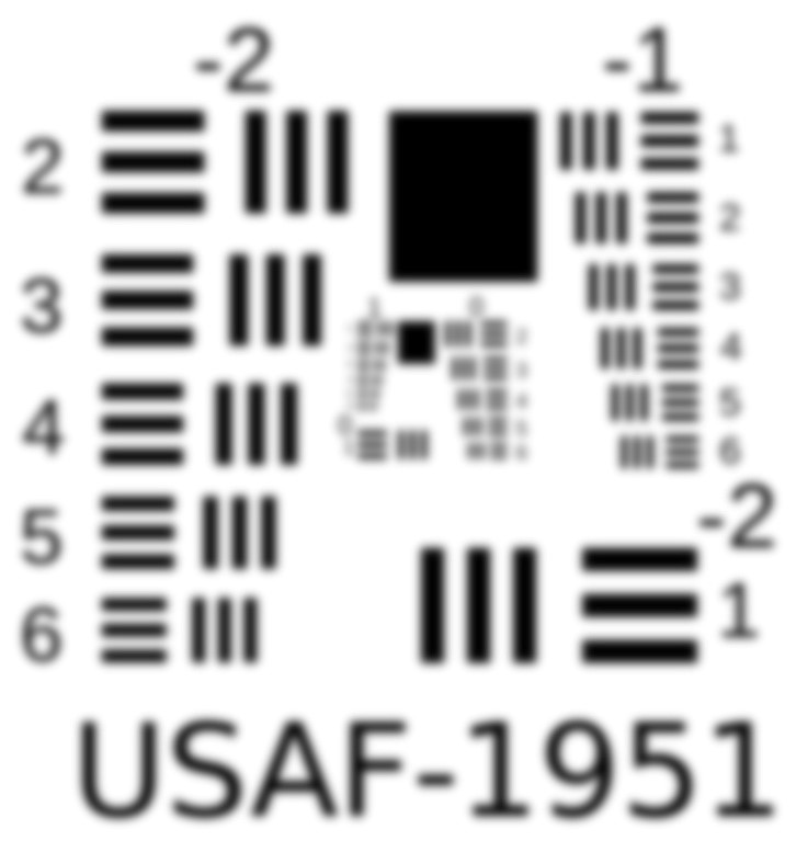
In the case of Cubesat camera resolution, it is all about the transfer of contrast from the original object to the image plane at a specific frequency. Each part of the filtering chain does have a direct filtering effect and determines the amount of contrast transferred. Figure 2 shows the low-pass filter effect on a 1951 USAF resolution target (Figure 1), while Figure 3 shows the effect due to the motion of the imaging system. The high-frequency cut-off is visible as a blur within these images.
These low-pass filtering examples of the USAF resolution target are a good reason why a CubeSat Camera’s sampling frequency resolution, like GSD, is not a suitable parameter to specify the imaging performance.
The Figure-of-Merit for CubeSat Camera Resolution
Modulation Transfer Function (MTF) is an effective way to describe and specify image quality as it measures how faithfully it transfers detail from the object to an image. While GSD is a pure geometric translation of the pixel size relative to the orbital height and focal length ratio, MTF incorporates resolution and contrast into a single specification. Therefore, MTF is a very powerful tool to describe CubeSat Camera Resolution as it can be cascaded to combine the influences of all the elements within the imaging chain.

The MTF of the optics includes the effects of diffraction within the system and aberrations at various spectral wavelengths. The cut-off frequency, where the MTF is zero, is given by ξc = 1/λ f#. The system transfers no contrast above this frequency. Furthermore, MTF is a good measure to evaluate the system’s performance at specific spectral wavelengths.
When comparing and evaluating the MTF of different optical systems, it is important to note:
- the MTF across the image plane, on-axis and off-axis. Manufacturers frequently only list the on-axis performance;
- the MTF at the shorter and longer wavelengths across the spectrum. Many MTF plots only show the polychromatic performance across the spectrum;
- the through-focus MTF is also a great tool to evaluate the system’s sensitivity to focal shifts and see how the various wavelengths’ focal points differ.
- MTF can also be used to evaluate the influence on the performance of thermal variations across the system
Understanding the Spatial Frequency
For the unique reconstruction of a sampled image, the Shannon sampling theorem requires a uniform sample spacing equal to no less than ∆x = 1/2kn where kn is the highest resolvable spatial frequency contained in the image. The sampling rate at twice the highest spatial frequency is known as the Nyquist rate. Any spatial frequencies below the Nyquist frequency are unambiguously reconstructed, while the system may alias spatial frequencies above the Nyquist frequency to a lower frequency. In this case, aliasing may appear as a Moire pattern.
Spatial frequency is often expressed in terms of line pairs per millimeter or cycle per millimeter.

Regarding CubeSat Imager resolution, one can think of line pairs in terms of the sensor’s pixels, where a single line pair corresponds to two pixels. One needs two CubeSat Imager pixels for each line pair or cycle. Therefore, one must always determine the Nyquist frequency in terms of two pixels. This implies the number of pixel pairs within a millimeter.
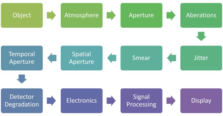
The Components Degrading CubeSat Imager Resolution

- Atmosphere – atmospheric scattering, absorption, and turbulence directly impact the systems MTF where aerosols in the atmosphere and absorption have the most significant impact.
- Aperture Diffraction – diffraction MTF is a wave-optics calculation for which the only variables are the aperture diameter, spectral wavelength, and focal length. In many cases, this parameter determines the upper limit of the optical system’s performance when aberrations are negligible.
- Optical Aberrations & Defocus – lenses are not ideal and may focus light rays at slightly different places due to spherical aberrations; furthermore, defocus within the system impacts MTF even further.
- Jitter – this can be seen as high-frequency random motion, with deviation periods lower than the effective pixel integration time.
- Motion or Smear – lower frequency motion, with movement periods higher than the effective pixel exposure time. For a line scan system, one would expect a single-pixel smear within the flight direction. This motion degrades the MTF by nearly 36% in the along-track direction. If the relative motion within the across-track direction is zero, no effect is visible on MTF.
- Spatial aperture – the two-dimensional trapezoidal spatial quantization of square pixels in the image plane
- Temporal Aperture – Degradation due to the relative motion between the target and image plane, and TDI synchronism error between the target motion and the TDI image plane electronic scan rate and discrete charge motion effects (CCD only)
- Detector Degradation – the rectangular shape, regular spacing, and aperture of pixels directly impact the MTF and is calculated using a sinc function. Variations in pixel-to-pixel spacing may also impact MTF but is, in many cases, negligible.
- Amplifier and Readout Electronics – variations within the amplification, readout of charge or electrons, and signal filtering have a further impact on MTF.
- Signal Processing – Image correction, calibration, and processing, like denoising or sharpening, may directly affect MTF.
The xScape100 Optical Front-End MTF Performance
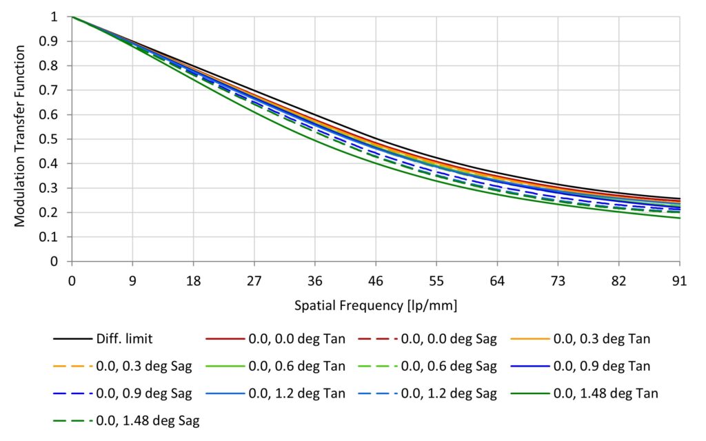
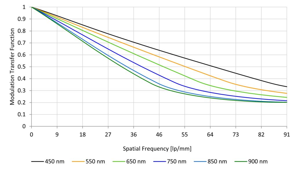
The xScape100’s VNIR optical front-end is a F6.1 system with a 95 mm aperture and 580 mm focal lengths. This is a reflective system with a font obscuration (47.2 mm diameter). The system’s Nyquist frequency is 91 lp/mm and was designed to achieve a 4.75 m GSD at 500 km. One should also note that the Ground Resolved Distance (GRD) is 3.57 m for a 500 km orbital height and at a wavelength of 550 nm. This GRD drops to about 5.77 m at a wavelength of 900 nm.
The following graphs provide an overview of the optical front-end’s MTF performance:


